| |||||


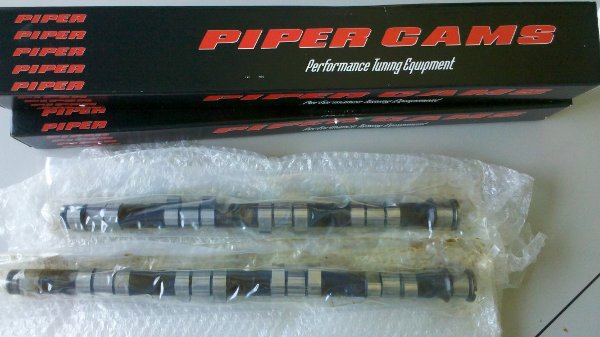
Piper camshaftsOne of the things I've been wanting to try is a set of different camshafts. The problem is which camshafts to choose. There are not a lot of good before/after tests of camshafts for the Speedster, and I've seen some interesting problems with some brands. So in the end I decided to go for a regrind. Why? Because that is the only way you can be reasonably sure the sprockets will be placed in the same position on the cam as intended by the factory. It removes 1 uncertainty factor. And a regrind with roller cams is not much of an issue.So I got a spare set of original cams and sent them to Piper to be processed. I got them back after about 1,5 weeks, nicely packed in a boxes.
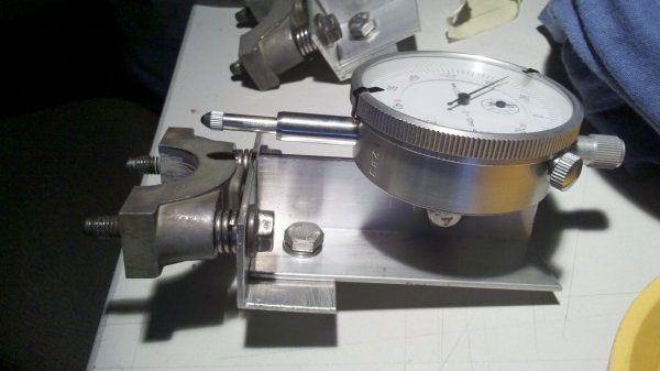
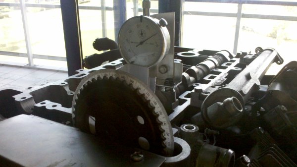
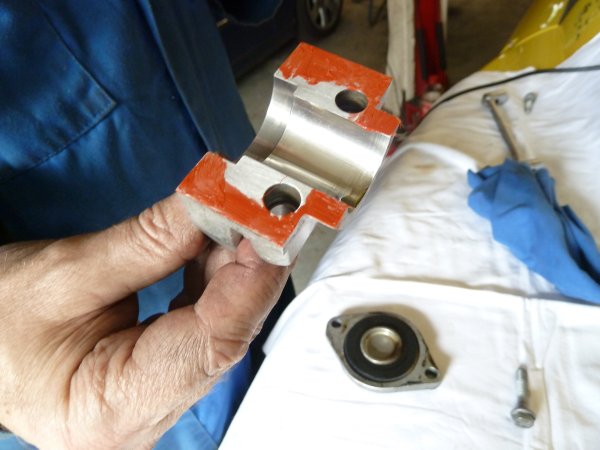
Before fitting the cams to the engine, I wanted to take some measurements. I have a spare engine which I wanted to use for that. I tried fabricating a setup that would be able to repeatable give the same measurement results. I used two of the upper bearings to attach an dial and a indicator to.
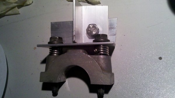
Both are then placed on the engine.
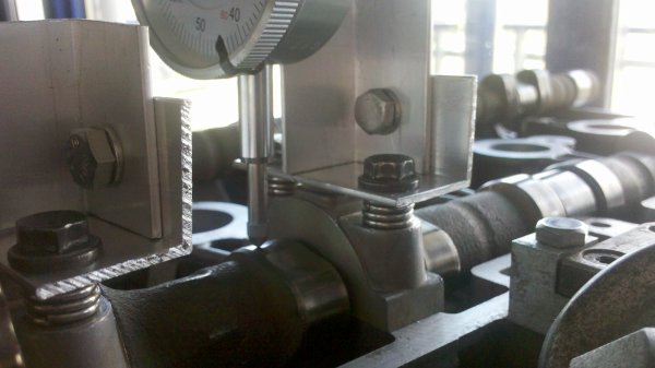
I printed a degree wheel, cut it out and glued it to the sprocket. With that in place, the indicator shows the position of the camshaft.
After trying a few measurements and removing and installing the cams again, the measurements seemed to be pretty reproducible, within 0.01mm. So then the interesting task begun:
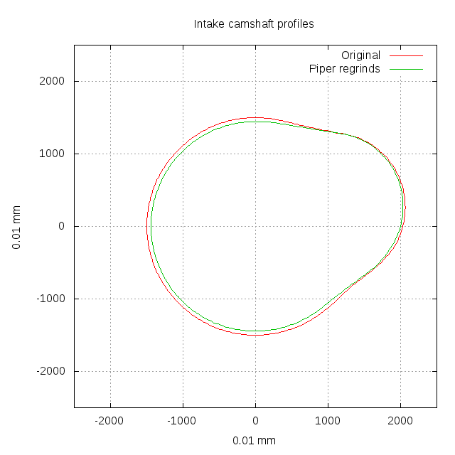
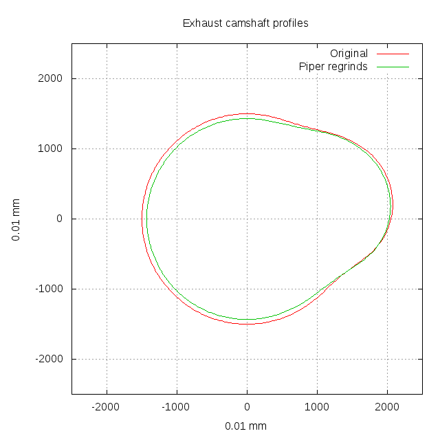
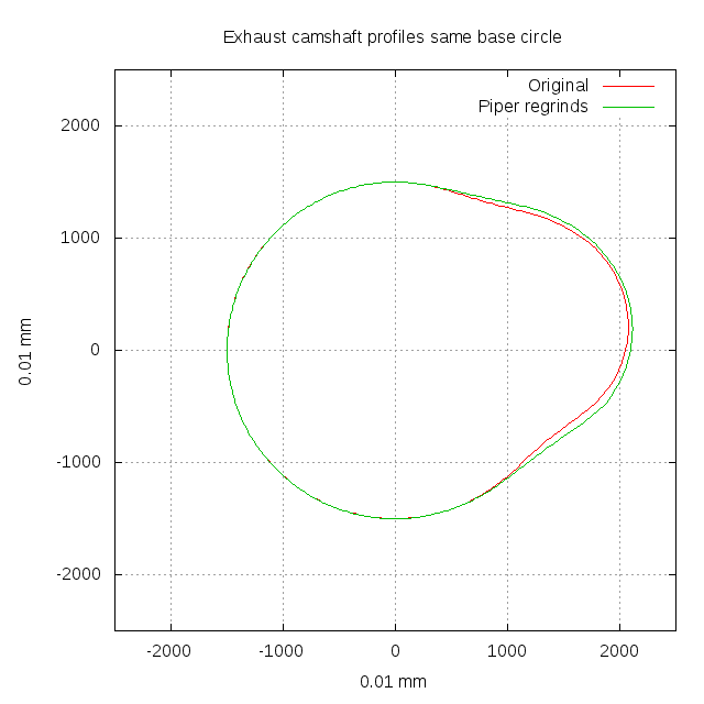
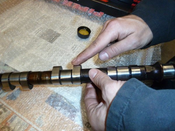
I also measured the base circle of both camshafts. The Piper camshafts have a smaller base
circle, making the difference between the base circle and the top of the lobe larger. Because
the engine uses hydraulic lifters this is not a problem.
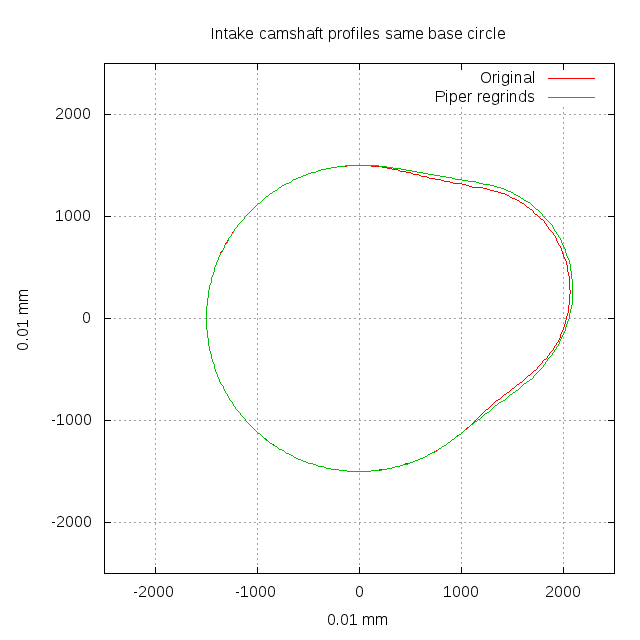
You can clearly see that the Pipers have a smaller base circle. However, this drawing gives a poor idea of the change in lift and duration compared to the original camshafts. So I plotted a second set, this time with the same base circle.
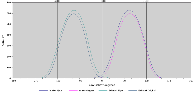
Based on the same information I also plotted out the camshaft lift over the cycle of the engine for all camshafts.
The picture clearly shows the differences between the camshafts. From the spreadsheets I also calculated a number of different characteristics of the camshafts. They are:
So the velocity and acceleration figures for the Pipers are a bit better, less wear on the valve train.
Then there is the issue of duration. This is a tricky bit, because different companies measure
duration starting at different lifts. Obviously the duration is shorter when you start measuring
at 0.08mm lift then at 0.02mm lift.
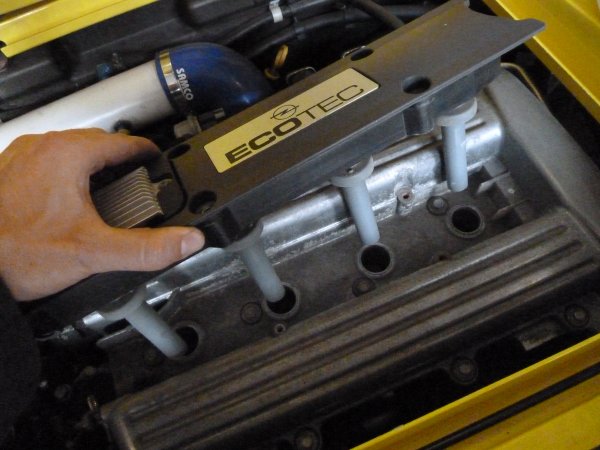
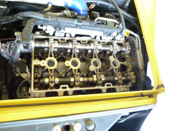
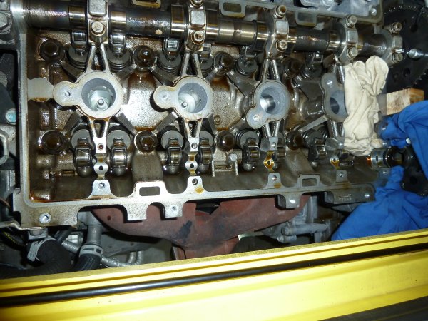
So, based on the measurements you would actually suspect a measurable change in engine power output. On to fitting the cams on the engine. Basically, start by unplugging the connector and removing bolts so you can remove the ignition unit.
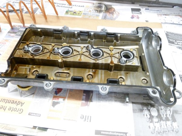
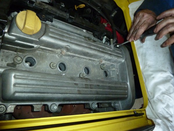
Remove the screws so the cam cover can be removed.
Inspect the gasket to see if it is ok and can be reused.
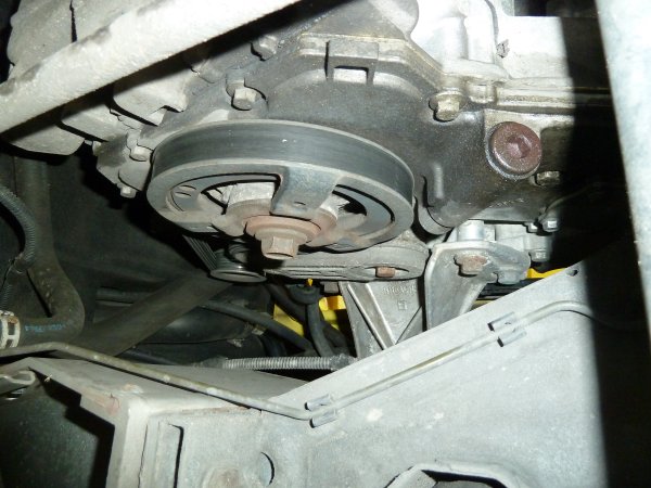
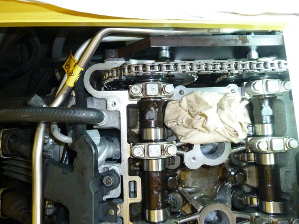
Rotate the crankshaft so the markings align.
Remove the chain guide.
And loosen the camshaft bolts.
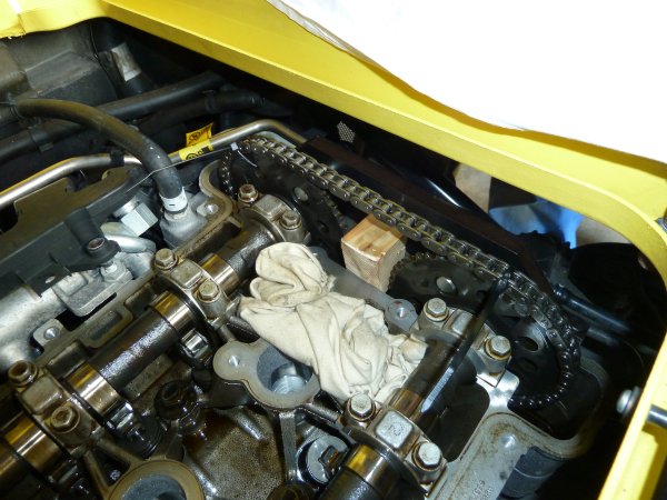
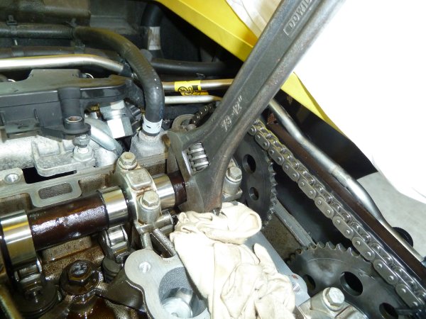
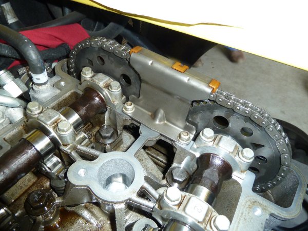
Place the sprocket locking tool and, if you want, put a piece of wood that securely fits between the sprockets. We also tiewrapped the sprockets to the chain.
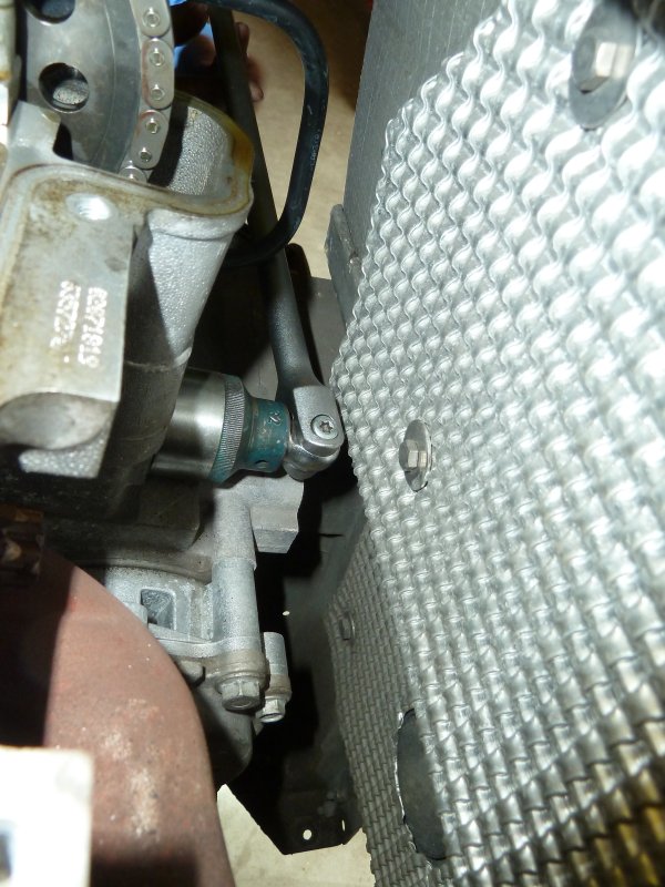
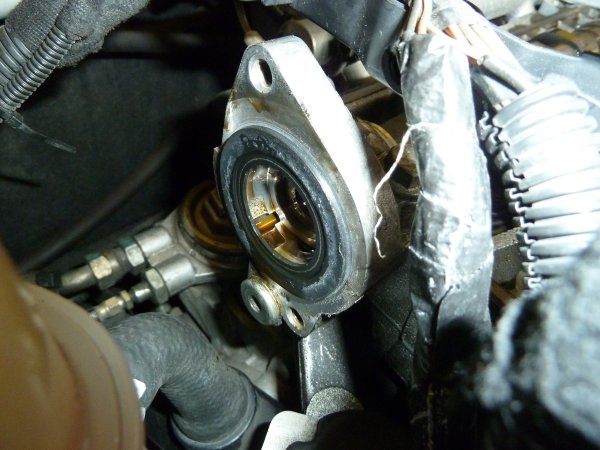
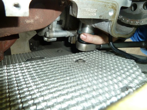
Break loose the chain tensioner.
And remove it.
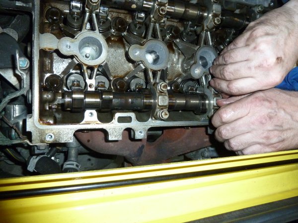
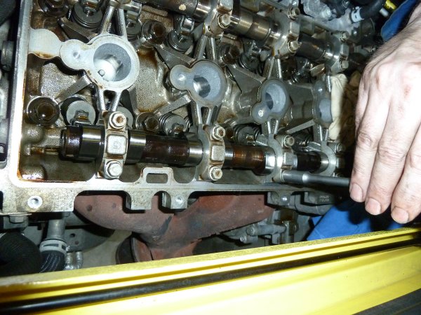
Loosen the bolts holding the bearing caps in place bit by bit in a circular motion from the outside in, loosening each bolt a bit further each time. Then remove the bearing caps.
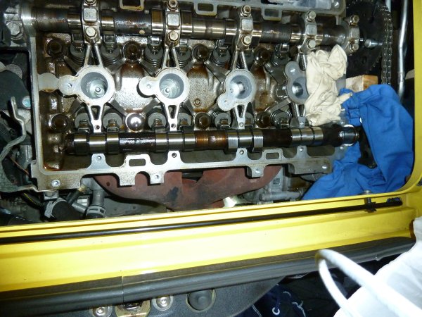
Remove the exhaust camshaft bolt and remove the camshaft.
Get the new exhaust camshaft and put some engine oil on it.
Now put the exhaust camshaft back in. Make sure all the rockers are straight! They will be destroyed (with obvious chance of engine damage) if you don't.
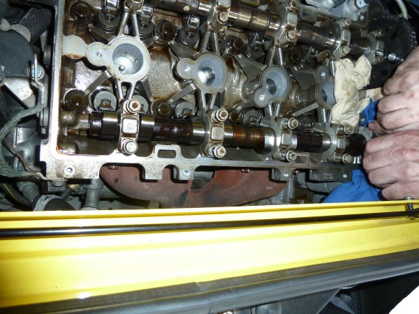
Replace the bearing caps.
And tighten the bolts in a circular motion from the inside out, bit by bit.
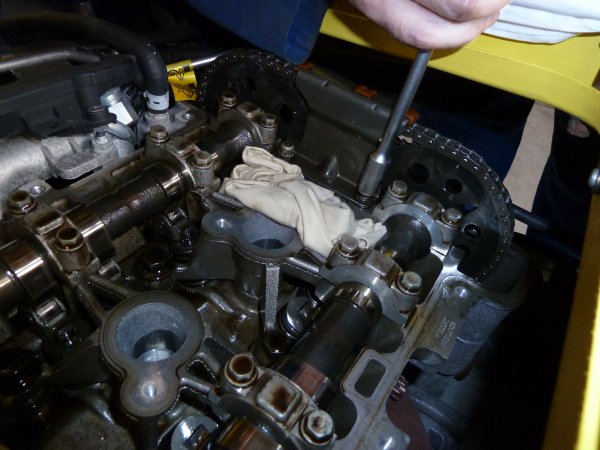
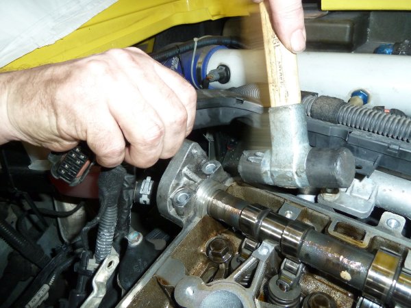
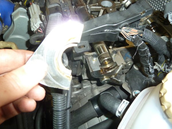
The intake camshaft is basically the same procedure. However there is is an extra bearing cap to remove, which can be difficult because there are aligning pins in place.
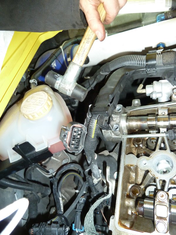
After removing the bolts, gently tap it with a soft hammer, alternating sides.
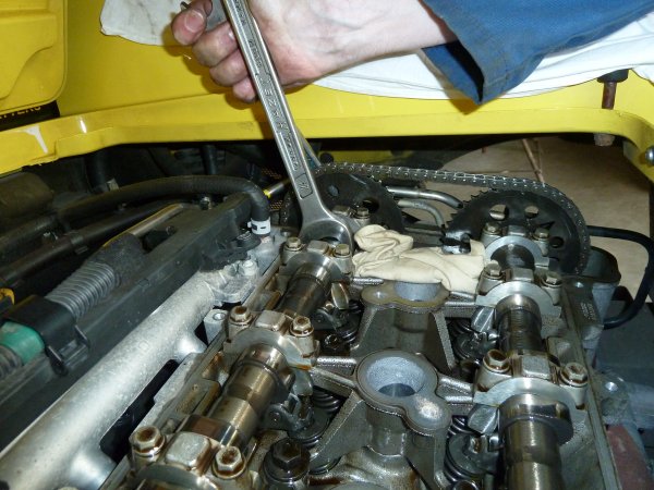
As soon as there is room, add a flat screwdriver in the gap and continue tapping on alternating sides, increasing the gap.
After a bit you can remove the cap.
Now proceed replacing the intake camshaft just like the exhaust camshaft.
And tighten the bolts of the bearing caps.
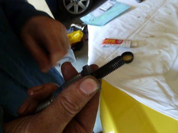
Use new camshaft bolts (these are stretch bolts, so they should not be reused).
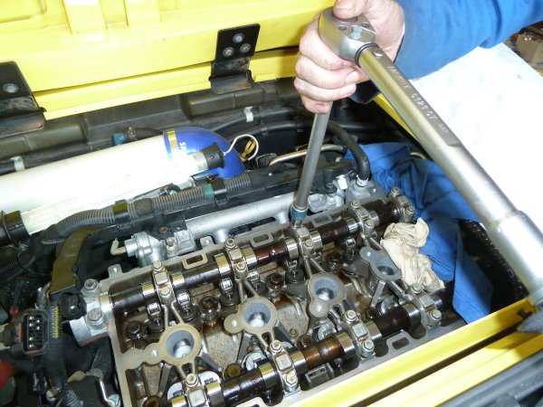
And tighten the bolts (85Nm, 15°, 30°).
The timing tool and the bit of wood can be removed.
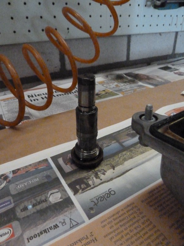
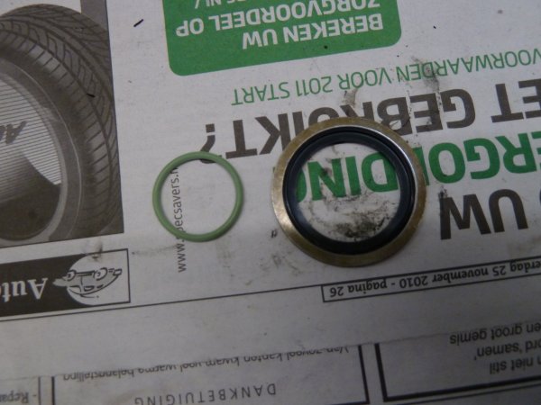
Unpack the new seal rings for the chain tensioner.
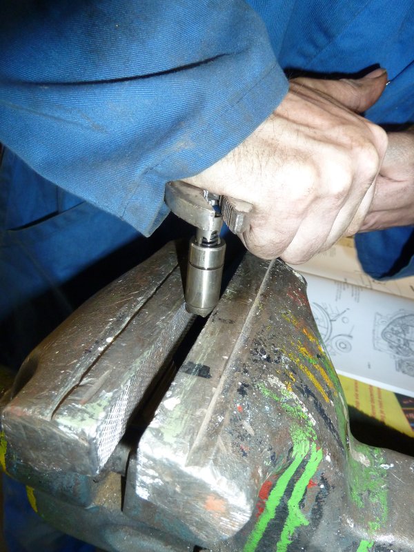
Compress the tensioner so it is locked in the down most position.
Place the tensioner back in the engine.
Now, the tensioner needs to be compressed so it will unhook from its compressed position and put force on the chain.
Remove the tiewraps. Now it is smart to check the rotation of the cams and the positioning. Rotate the crankshaft a couple of times (using a ratchet) and verify the timing. Place the chain guide.
Put the cam cover back on.
And replace the ignition. The installation is done now. After checking everything over, the engine could be started. Although rollers are used it might be advisable to raise the RPM to around 2000 after starting and keeping it there for a while. This reduces stress on the valve train. | ||||||||||||||||||||||||||||||||||||||||||||||||||||||||||||||||||||||||||||