| |||||


EGR simulator2010/04/26 update To get more background on what impact this change has on the engine and ECU, read my blog posting on the EGR system.
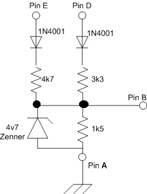
On the Z22SE forum they developed a circuit to replace the EGR (exhaust gas recirculation valve). This will let the ECU think the EGR is still there, while it isn't. The circuit looks like this.
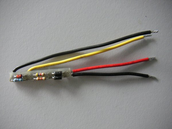
After buying the parts it was time for some soldering with the following result.
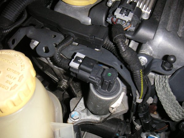
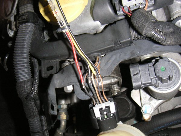
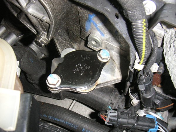
Then the simulator could be mounted in the car. This is the EGR valve.
I'm going to place the simulator in parrallel. If there are any problems
I can reconnect the connector to the EGR (after removing the simulator).
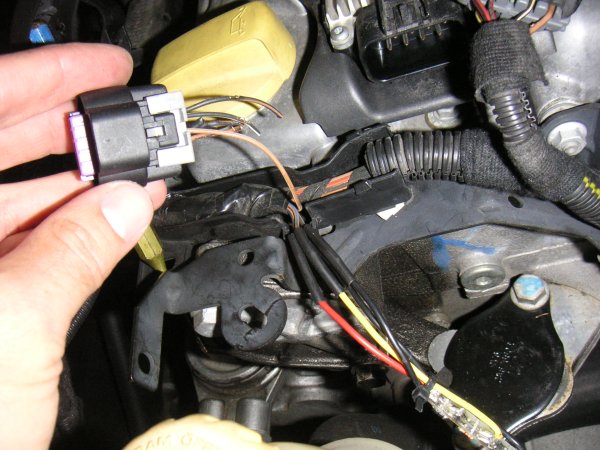
If there are no problems after a period of time, I'm going to cut of the
connector and solder the simulator directly to the wires.
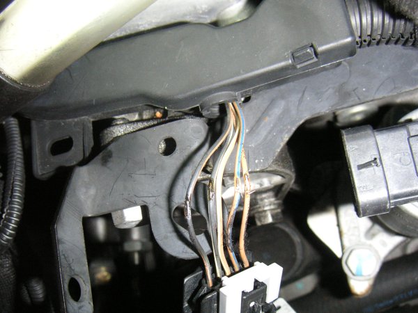
I stripped a bit of the isolation of the wires (except the middle one) and put solder on them.
Then I soldered the simulator to the wires. The colors (according to the forum) are:
Pin A: brown After soldering it looks like this.
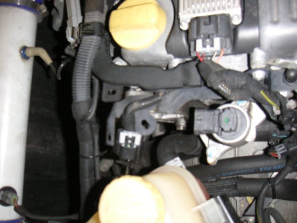
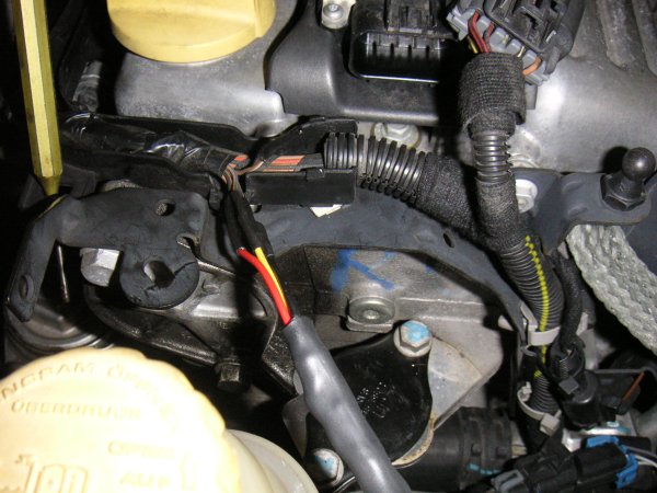
Last step is isolation. As it is a temporary setup for me I put tape on the connectors to prevent water ingress and tiewrapped the simulator to a hook that is connected to the engine.
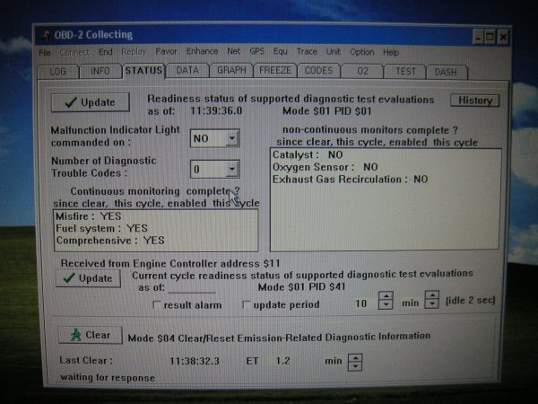
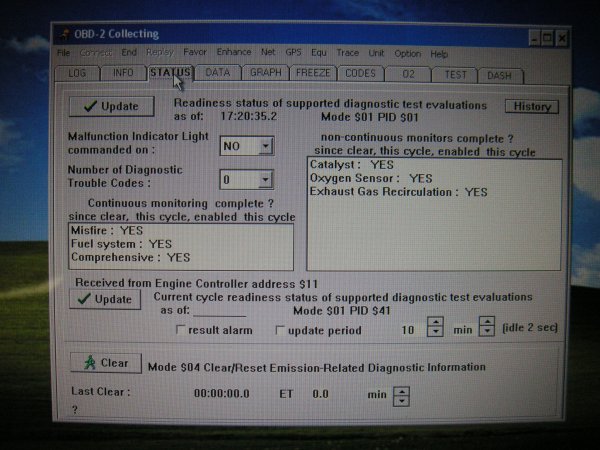
To be sure the ECU wouldn't have problems with the circuit I used the diagnosis software to reset the longterm test. All tests will have to be redone, including the EGR test.
After a testdrive of around 150km the screen looked like this:
All tests passed, including the EGR test! No logged codes, so it all seems to function fine. After about 2 weeks of driving I will remove the connector and do the final install of the simulator. After that the EGR valve will be removed.
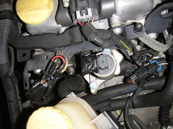
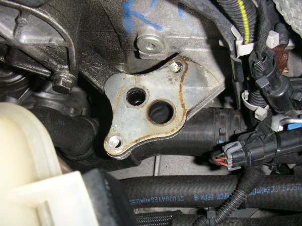
2007/08/26So time to remove the EGR valve. After removing two bolts it just comes off.
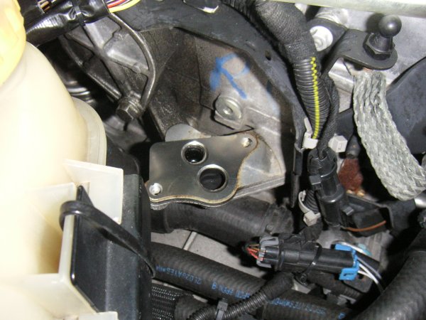
Then you need to fit the blanking plate. GM part number: 58 50 526 and optionally a gasget (don't know the partnumber, got it with the plate).
Put the gasget on first.
Then put the blankingplate on there.
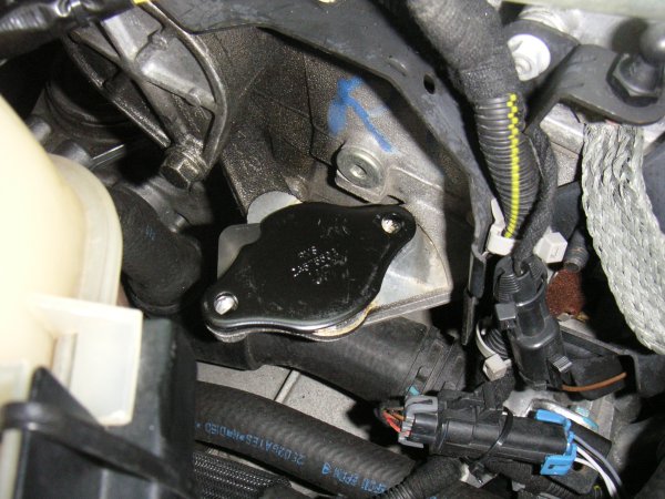
And bolt it all in place.
That's it, now no exhaust gasses can get to the intake manifold.
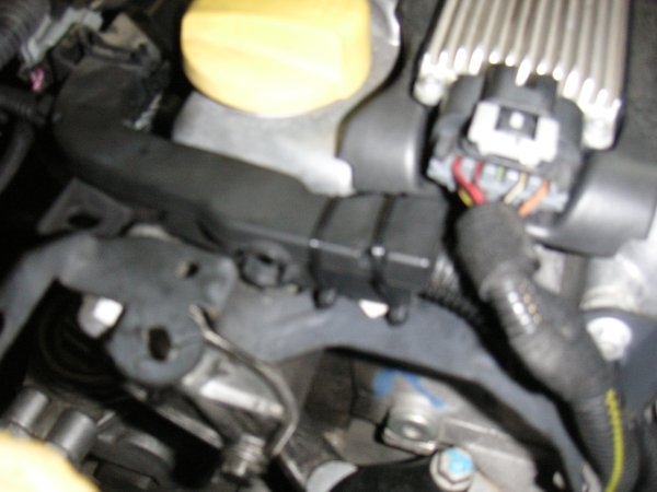
2007/09/26As an extra I decided to move the EGR simulator over to the cable guide so it is totaly out of view and the connector can be removed.First I soldered all the wires directly to the simulator instead of parallel to the connector. And ofcourse insulated the connections.
Then put the whole EGR simulator in shrinktube so it is completely isolated.
As it is all quite a tight fit I had to tiewrap the cable guide closed. At least it looks a lot cleaner :).
|